So, where to start?
After some random walk, what I found that worked best for me is reading the following book:
"Make: Electronics - 3rd ed." by Charles Platt
The book is designed for someone who has no idea about electronics at all. It is very hands-on, and you get your hands dirty from day one.
I am also using the following excellent books as reference manuals:
"The art of electronics - 3rd ed." by Paul Horowitz and Winfield Hill
"Practical electronics for inventors - 4th ed." by Paul Scherz and Simon Monk
So far, here are some topics that do not scare me as much anymore (covering Section 1 and Section 2 of Make: Electronics):
- How to use a multimeter: I think I got the basics right. Someone who doesn't know what they're doing might fry something! For example, measuring current requires the multimeter to become part of the circuit so that current flows through it, while measuring voltage is done by putting the multimeter in parallel with the portion of the circuit where a voltage drop is to be measured.
- How to use a breadboard: You must understand how the underlying tracks are laid out before plugging components. One common mistake is that I plug in a component horizontally, therefore shorting its terminals.
- How to light up a LED: An incredibly satisfying result for someone who doesn't even know what a 1.5V battery is. Several valuable lessons are learned, including:
- i) if you short the battery, electrons flow like crazy back into it, depleting it fast and possibly causing overheat and explosion;
- ii) you need a resistor to, well, resist the flow of electrons; if the resistor is large enough, you won't burn the battery. I don't know how much current a battery can tolerate, it probably depends on its rating;
- iii) a LED is not a simple component, and you must do your calculations before trying to light it up. A common LED needs a minimum voltage to light up, apparently from 1.2V up to 3.6V, which is also why I couldn't get a LED to light up when I used a single 1.5V battery once. Also, not too much current must flow through it or it will burn, so you need a series resistance to control the amount of current. The ensuing calculations were not trivial for me, and probably deserve their own post.
- How to use a switch: Switches come in all shapes and sizes (push buttons, sliders, SPST, SPDT, relays, etc.) and they are all very well covered by dedicated sections in the books above.
- Capacitor basics: Not super confident here, but I understand the idea. This is what I remember, might be wrong: Empty capacitors act like short circuits, but when you apply a voltage across them they charge up like $1-e^{-t}$. When they are fully charged, they act like an open circuit and nothing goes through, except high-frequency signals (e.g. current peaks). In this sense, you can see them as high-pass filters. Since they are essentially charge storages and they have their own discharge time, they can be used to get a fade-out effect for a dying LED.
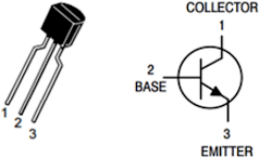
- Transistor basics: How BJTs operate in practice, although only in the standard regime, i.e. no reverse bias, saturation, cut-off, etc. I can understand why they are useful as switches (they can switch much faster than a relay, and they require much less voltage and current), but I still don't understand their use as amplifiers. What do people mean by "amplifier"? I can already get high current by using small resistances, and what the transistor does is just let the current flow. Why is everybody saying that the transistor "amplifies" the current?
I stopped reading the book after Section 2, because there are too many things I am not satisfied with. I will address them and report.
I have the suspicion that "fry" will be a commonly used term around here.
Comments
Post a Comment